Pin Posts and Placement: Specs That Prevent Spin and Failures
Approved artwork can still fail in wear testing
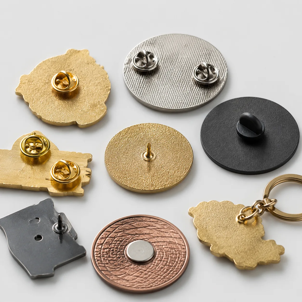
Many custom pin complaints start after the front side is fully approved. Color, plating and enamel may all pass, yet the finished item rotates on fabric, hangs off-angle, bends during packing, or snags lightweight garments. Those are usually not decoration failures. They come from an underspecified attachment system: too few posts, the wrong post diameter, weak post joints, poor post placement, or a clutch type that does not match the badge weight and fabric.
For importers, distributors and brand buyers, this is expensive because the correction is rarely just a note on the PO. If a 35 mm badge was tooled with one centered post and should have had two posts spread across the body, the supplier may need a revised back die, a new mold insert, an updated solder fixture, and a new PP sample. In normal production, that adds about 5-12 calendar days before bulk can restart, and it also creates mixed-stock risk if part of the order was already carded or packed.
The correct decision is not simply single post versus double post. It is a mechanical design choice based on six variables: finished size, metal thickness and final weight, center of mass, shape geometry, intended fabric, and wear frequency. For most enamel pins and metal badges in the 20-60 mm range, getting those variables right at RFQ stage prevents the majority of spin, droop, bent-post and fabric-damage claims.
Set post count from size, weight and center of mass
Post count should follow load and leverage, not factory habit. A 20 mm stamped iron pin at 1.2-1.5 mm thickness and 4-6 g can usually perform well with one centered post. A 40 mm die-cast zinc alloy badge at 2.0 mm thickness and 16-22 g is commonly unstable on one post even when the front outline looks compact. Width, height and center of mass matter as much as nominal size.
As a practical rule, one post is generally reliable for balanced shapes up to 25 mm and under about 8 g. From 26-32 mm, one post is acceptable only on compact round or square collectible pins with low wear frequency; two posts are safer for most wearable programs. From 33-45 mm, two posts should be standard on enamel pins, service awards and recognition badges. Above 45 mm, buyers should compare two posts, three posts, brooch bars and magnetic systems rather than defaulting to a standard pin layout.
Shape can override size. A 30 mm round pin may remain stable on one centered post, while a 30 x 18 mm horizontal logo plate, ribbon bar or flag shape can rotate noticeably because leverage is spread laterally. Top-heavy mascots, asymmetrical silhouettes, cutout designs and layered badges are especially prone to crooked wear if post count is chosen only by width.
| Finished size / build | Typical unit weight | Recommended attachment | Main risk if underspecified | Indicative FOB at 500 pcs |
|---|---|---|---|---|
| 15-20 mm, stamped iron/brass, 1.2-1.5 mm | 3-7 g | 1 post, 0.9 mm dia, butterfly clutch | Low if centered and balanced | USD $0.35-$0.60 |
| 21-25 mm, stamped or die-struck, 1.2-1.5 mm | 5-10 g | 1 post for round/square; 2 posts for wide shapes | Rotation on knitwear, slight droop | USD $0.45-$0.75 |
| 26-32 mm, soft enamel, 1.5-1.8 mm | 8-15 g | 2 posts preferred, 0.9-1.0 mm dia | Crooked hang, spin during wear | USD $0.55-$0.95 |
| 33-45 mm, enamel badge, 1.5-2.0 mm | 12-22 g | 2 posts standard, 1.0 mm dia | Bent post, clutch loosening, tilt | USD $0.80-$1.40 |
| 46-60 mm, thick cast badge, 2.0-3.0 mm | 20-40 g | 2-3 posts, brooch bar or magnet depending use | Fabric pull, sagging, user complaints | USD $1.20-$2.40 |
For 2026 sourcing, standard MOQ is still commonly 100 pcs per design, with better unit economics at 300, 500 and 1,000 pcs. Adding a second post usually changes FOB by only about USD $0.01-$0.05 depending on size and clutch style. That delta is usually negligible compared with the cost of one QC hold, one rework cycle or one failed uniform rollout.
Specify post diameter, exposed length and joint construction
Many RFQs describe Pantone colors and backing cards in detail but say nothing about post diameter. That is a preventable gap. Common post diameters are 0.8 mm, 0.9 mm, 1.0 mm and 1.2 mm. The 0.8 mm option is usable on very small collectible pins, but it bends more easily during carding, bulk packing and transit. For most B2B wearable programs, 0.9-1.0 mm is the practical baseline.
A useful working rule is 0.9 mm posts for pieces under about 10 g, 1.0 mm posts for medium-weight pieces from roughly 10-22 g or for weekly wear, and 1.2 mm posts for thicker cast badges, heavier name badges or builds paired with locking clutches. The trade-off is garment impact: thicker posts are stronger but create a more visible puncture and are less suitable for silk-like fabrics, fine knits and premium shirting.
Exposed post length should also be written into the specification. For butterfly, rubber and deluxe clutches, 8.0-9.0 mm exposed length is standard. Below 7.0 mm, clutch engagement becomes inconsistent; above 10.0 mm, posts are more likely to bend in trays or polybags. A practical dimensional spec is post diameter ±0.05 mm and exposed length ±0.3 mm. For straightness, a workable criterion is no visible lean at 300 mm viewing distance and not more than 0.25 mm runout over an 8.5 mm exposed length.
If posts are soldered onto stamped parts rather than cast integrally, the joint method matters. The solder fillet should be continuous around the base with no visible lift, no cold-solder gap and no cracking after handling. On medium and large badges, post base pad diameter is often 2.2-3.0 mm, with solder coverage around at least 270° of the circumference. Loose or detached posts should be treated as major defects at minimum; on repeated-wear programs they are often managed as critical-to-use even if not regulatory-critical.
Place posts to resist rotation, not to decorate the back
Placement is where many otherwise good pins fail. A centered post may look clean on a proof, but it provides minimal resistance to rotation on a wide logo plate or offset shape. For two-post layouts, the objective is to spread posts across the load path while keeping enough metal around each post base so the back does not weaken near the edge.
For most 25-45 mm horizontal badges, post spacing equal to 55-70% of total width center-to-center is a reliable baseline. Minimum edge distance should usually remain 4-6 mm from the nearest outer edge on small and medium pins, and 6-8 mm on heavier cast parts. On a 35 mm wide badge, that usually means two post centers 20-24 mm apart, with each post center about 5-6 mm in from the side edge.
Vertical position matters as well. On top-heavy shapes, shifting the post line 1-3 mm above the geometric center can reduce forward droop by moving support closer to the actual center of mass. On tall narrow designs, top-and-bottom placement may improve anti-sway performance, but it reduces user convenience and complicates backing card layout. For most corporate logos, service awards and recognition pins, a left-right layout remains the simplest stable arrangement.
A concrete example is more useful than a generic note. If a 32 x 20 mm rectangular badge weighs 12 g and is intended for weekly wear on a uniform shirt, a workable back specification would be: two 1.0 mm posts, exposed length 8.5 mm, spacing 21.0 mm center-to-center, each post center 5.5 mm from the side edge and 10.0 mm from the bottom datum. That is far better than a proof comment saying only '2 posts on back'.
Back-view proofs should always show post centers dimensioned from at least two reference edges. A typical note is: left post center 5.5 ±0.5 mm from left edge and 10.0 ±0.5 mm from bottom datum; right post mirrored. Those dimensions let the factory build a repeatable jig and allow incoming QC to verify placement with calipers or a simple acrylic go/no-go gauge.
Match clutch and hardware to fabric, weight and wear frequency
A good post layout can still underperform if the clutch choice is wrong. Butterfly clutches are the economical default and are acceptable for many promo pins, but they can loosen after repeated use and are less forgiving if the post is slightly bent. Rubber clutches are easy for end users and reduce scratching, yet their retention is usually weaker on heavier badges. Deluxe and locking clutches improve holding force, but they add cost, can slow packing, and may be unnecessary on low-value giveaways.
Fabric should drive the recommendation. On jackets, uniforms, denim, canvas totes and other medium-to-heavy textiles, 0.9-1.0 mm posts with butterfly or locking clutches usually perform well. On lightweight knitwear, dress shirts or premium garments where puncture damage matters, standard posts may be the wrong hardware even if the badge is visually small. In those cases, low-profile magnets can be suitable for pieces under about 12-15 g, provided the buyer confirms magnet restrictions in the target market and user environment.
Wear frequency changes the cost logic. A collectible pin that will remain on a backing card or display board can tolerate a simpler one-post build. An employee badge worn weekly, attached to uniforms, removed for laundering and repacked repeatedly should not be engineered to the same minimum standard. Upgrading from one 0.9 mm post with butterfly clutch to two 1.0 mm posts with deluxe clutches commonly adds only USD $0.05-$0.15 FOB per unit at 300-1,000 pcs.
Lead-time impact is modest when hardware is specified early. Typical PP sample lead time is 5-8 days after artwork approval. Bulk production is commonly 10-18 days for standard soft enamel pins and 12-20 days for thicker die-cast badge builds. Add 2-4 days for special clutches, magnets, custom brooch hardware or more complex cast bodies. If the hardware change requires tool revision or a new back insert, add roughly 3-7 more days.
Write measurable QC criteria for sampling and incoming inspection
Instructions such as 'use two posts for stability' are too vague for production control. The specification should state measurable values: post count, diameter, exposed length, location, hardware type, finish requirement and functional performance. A clear example is: 2 posts, 1.0 mm diameter ±0.05 mm, exposed length 8.5 ±0.3 mm, center spacing 22.0 ±0.5 mm, butterfly clutch, nickel-free plating, post centers 5.5 ±0.5 mm from left and right edges.
Functional testing should also be defined. For wearable badges, a practical acceptance method is a fabric-hang test on a 1.0-1.5 mm medium-weight woven panel, approximately 180-240 gsm. After 20 attach-remove cycles, the badge should remain within 10° of intended orientation, with no detached post, no clutch disengagement under normal handling and no visible post bend. For repeated-wear employee programs, increase the cycle count to 50. For locking-clutch builds, add a removal-and-refit test to confirm the post tip does not mushroom or deform.
AQL should reflect commercial risk. AQL 2.5 major and 4.0 minor remains common for custom metal promotional products, but bent, missing, loose, detached or significantly mislocated posts should be classed as major defects. Severe rotation during the agreed wear test should also be major. Minor defects may include slight cosmetic variation in back-side solder appearance if function is unaffected. On high-visibility uniform badges, some buyers tighten major AQL to 1.5 because hardware failure is costlier than a small cosmetic enamel issue.
- Specify post count by SKU, not only in PO remarks
- State post diameter and exposed length with tolerance, e.g. 1.0 ±0.05 mm and 8.5 ±0.3 mm
- Dimension post centers from two reference edges on the back-view proof
- Define clutch type by style and material: butterfly, rubber, deluxe, locking or magnet
- State plating compliance requirements such as nickel-free if needed by market
- Classify bent, loose, detached or missing posts as major defects
- Require PP sample photos of both front and back with dimensions marked
- Keep one signed golden sample and one sealed limit sample for reorders
- Use a named fabric panel, cycle count and pass/fail rotation angle for wear testing
Know when standard posts are the wrong hardware
Standard posts are not the best answer for every project. If the item exceeds 50 mm, weighs more than about 25-30 g, includes layered metal parts, has moving danglers or spinners, or will be worn on delicate garments, forcing a conventional pin-post setup often creates avoidable complaints. In those cases, buyers should actively compare brooch bars, magnets, tie-tack style hardware or even a different product format.
One common failure case is the challenge-coin aesthetic converted into a wearable badge. A 50 mm zinc alloy piece at 3.0 mm thickness with deep relief can look premium in a sample box, but on two small clutches it often sags on a shirt placket, rotates on knitwear and leaves visible stress marks on the fabric. Another problem case is a dangler pin where movement adds dynamic leverage; even if the main body passes static wear testing, repeated motion can work clutches loose over time.
For soft luxury garments, hospitality uniforms and premium retail merchandise, magnets may outperform posts because they avoid puncture entirely. But magnets are not universal. They can slip on thick textiles, may be unsuitable around some medical or electronic environments, and usually add noticeable material cost. For heavier badges, a brooch bar often distributes load more effectively than simply adding a third post. The correct choice should be based on actual wear conditions, not the factory catalog default.
Use a short buyer workflow before artwork release
Before approving any pin or badge, run a mechanical review separate from the visual review. First, classify the item: collectible display pin, occasional-wear promotional pin, or repeated-wear badge. Second, check shape behavior: balanced, wide, tall, top-heavy or asymmetrical. Third, match hardware to use case: one post only for small balanced pieces, two posts for most medium wearable pins, and non-post hardware for heavy or fabric-sensitive applications.
Then lock the decision into the proof package. The supplier should confirm finished size, metal thickness, estimated weight, post count, post diameter, post spacing, edge offsets and clutch type before sampling starts. If the factory sends only front-view artwork, request a dimensioned back-view proof. That single step prevents many repeat orders from drifting back to the supplier's house-standard post placement.
For RFQ efficiency, buyers should send four inputs with the artwork: finished size, target thickness, intended wear orientation and expected fabric. With that information, a competent supplier can usually propose a realistic post layout, MOQ tier and FOB range before making the sample. For standard custom enamel pins, MOQ is commonly 100 pcs per design, with stronger pricing at 300, 500 and 1,000 pcs; sample charges are often credited against bulk orders; and broad FOB ranges remain about USD $0.35-$1.60 per piece depending on size, plating, enamel style, hardware and packaging. The extra 10 minutes spent specifying the back side is usually cheaper than one resampling cycle, one delayed shipment or one field complaint.
Have a project? Send your artwork and target quantity and we’ll reply with a detailed quotation within 12 working hours.
Ready to get this made?
Send your sketch, target quantity and ship-date. Detailed quotation in 12 hours.